Front-view of the almost fully integrated AUV (the only missing part is the hydrophone and the ultrasonic receiver for the demodulation of navigation and command messages): the two lamps supports 3 colors (white, blue and red) and must be switched on manually before diving. They are rechargeable over a water-sealed USB port.
Rear-view of the AUV: the white water conductivity sensor has a protection cap, which is removed in operation. There are two blank penetrators, which will be replaced by other sensors in future applications.
This is the support structure for the electronics. The USB hub with voltage converter is on the left upper side, while the Beaglebone board is on the left lower side. The thruster board with the ESP32 micro-controller and the second voltage converter is on the right upper side. The right lower side is empty and reserved for the battery.
The camera and laser guidance is built into the front transparent dome. The USB cable is connected to the Beaglebone Black via the USB hub and provides the video signal from the Full-HD camera (1920 x 1080) as well as the power for the two laser diodes. The two laser rays crosses approximately 25cm in front of the camera lens. An object in front of the camera at exactly this distance will only show a single red spot on its surface. Closer or farther away objects will show two spots. Moving closer to an object will either decrease or increase the distance between the two spots if the distance to the object is greater or smaller than the 25cm.
For component and software testing, a smaller-size unit was built with a cyclindrical transparent body and four thrusters, which are of the same type as for the final AUV. The unit contains only one battery pack and the ESP32 micro controller board.
AUV Test Unit
Another purpose of the Test Unit is to make simultaneous measurements of pressure, temperature, conductivity and the speed of sound at a frequency of 40kHz to establish an accurate model of the signal propagation in water at any depth.
The AUV has two hatches to get access to the front and rear inner space:
The front part contains the stereo camera mounted at the front window, two light sources and the main processor unit with the interface board to the sensors (temperature, pressure, conductivity) including GNSS.
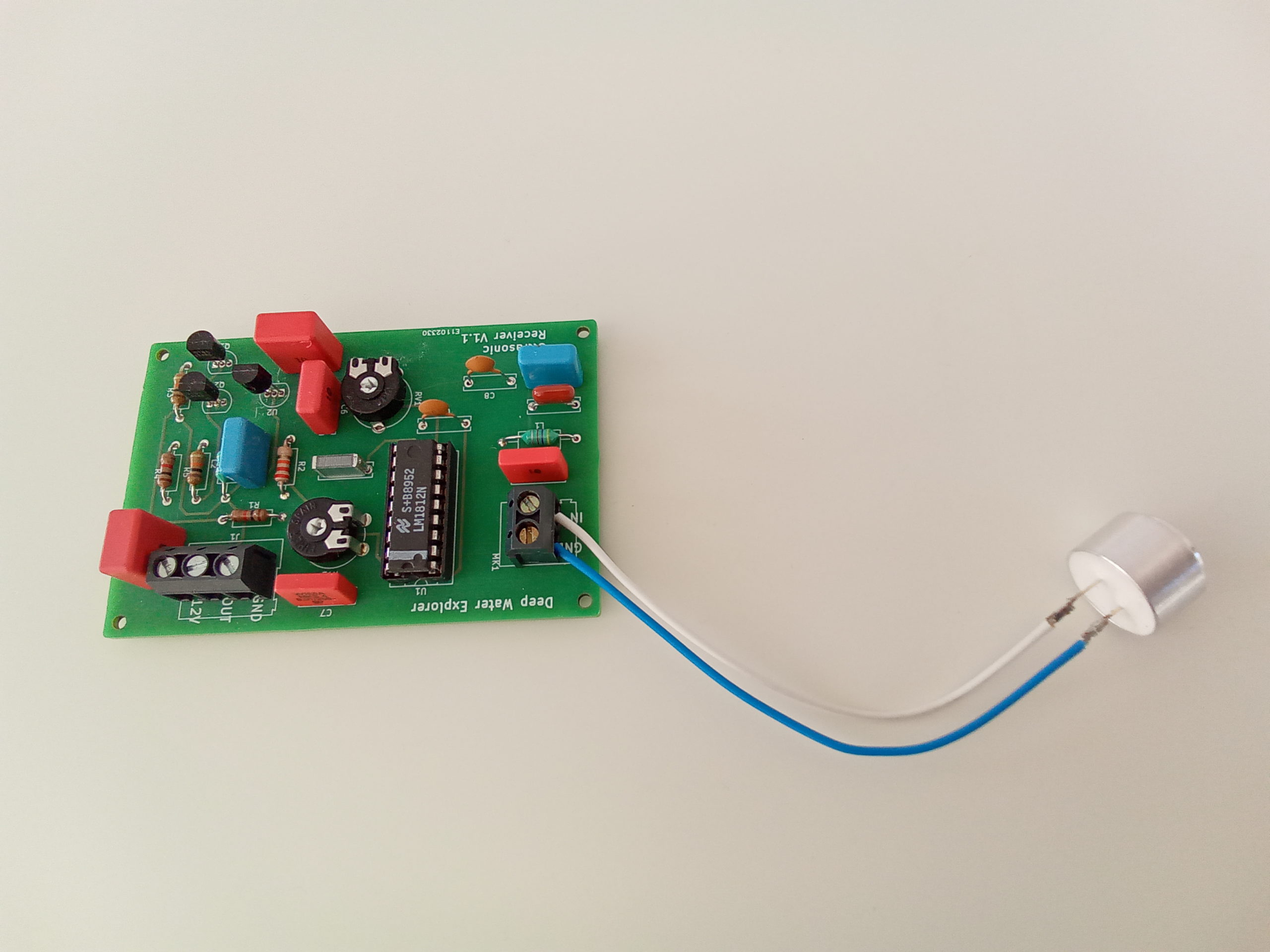
The rear part contains the two batteries (one is active, the other is backup) and the power management system, the controller for the four thrusters, the circuitry for the ultrasonic sender and receiver and the secondary processor unit.
The main processor unit (BeagleBone Black) is connected to the secondary processor (NodeMCU ESP32) over USB. The AUV can be accessed from the outside over Wi-Fi.
AUV without solar panel
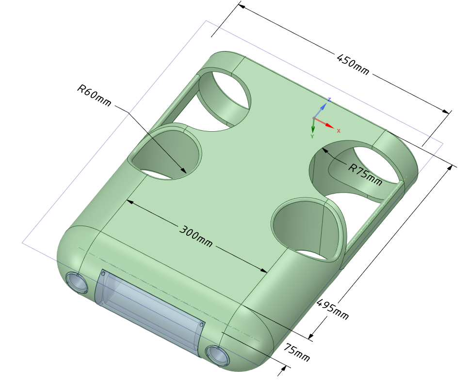
There are four mount points on the top of the AUV, which are used to mount the solar panels, which will be used to recharge the batteries when the AUV is on the water surface. The solar panel is connected to the power management system over a 4-pin connector on the rear side. This connector can be also used to provide power to the AUV over a long tether, which makes it possible to operate the AUV as ROV.
The transducer is located in the bottom center of the AUV, which is used in the swarm mode for sending ultrasonic signals to other AUV’s for localization purposes and in the single unit mode as echo sounder to measure the distance to the ground.
A thruster model with a depth rating of 300m was selected as an engine for the AUV. The operating voltage range is 12V – 24V and the speed can be controlled with a 50Hz PWM signal with a pulse width of 1-2ms. The integrated speed controller (ESC) must be initialized on every powerup:
Power on the ESC on the red and black connector. Three beep sounds indicates that the ESC has started up.
Apply a 1ms signal to the yellow connector. The ESC should respond with a beep.
Apply a 1.5ms signal to the yellow connector. The ESC should respond with a beep.
After two beep sounds , the initialization is completed.
Apply a 1-1.5ms PWM signal to the yellow connector to control the thrust in one direction.
Apply a 1.5-2ms PWM signal to the yellow connector to control the thrust in the other direction.
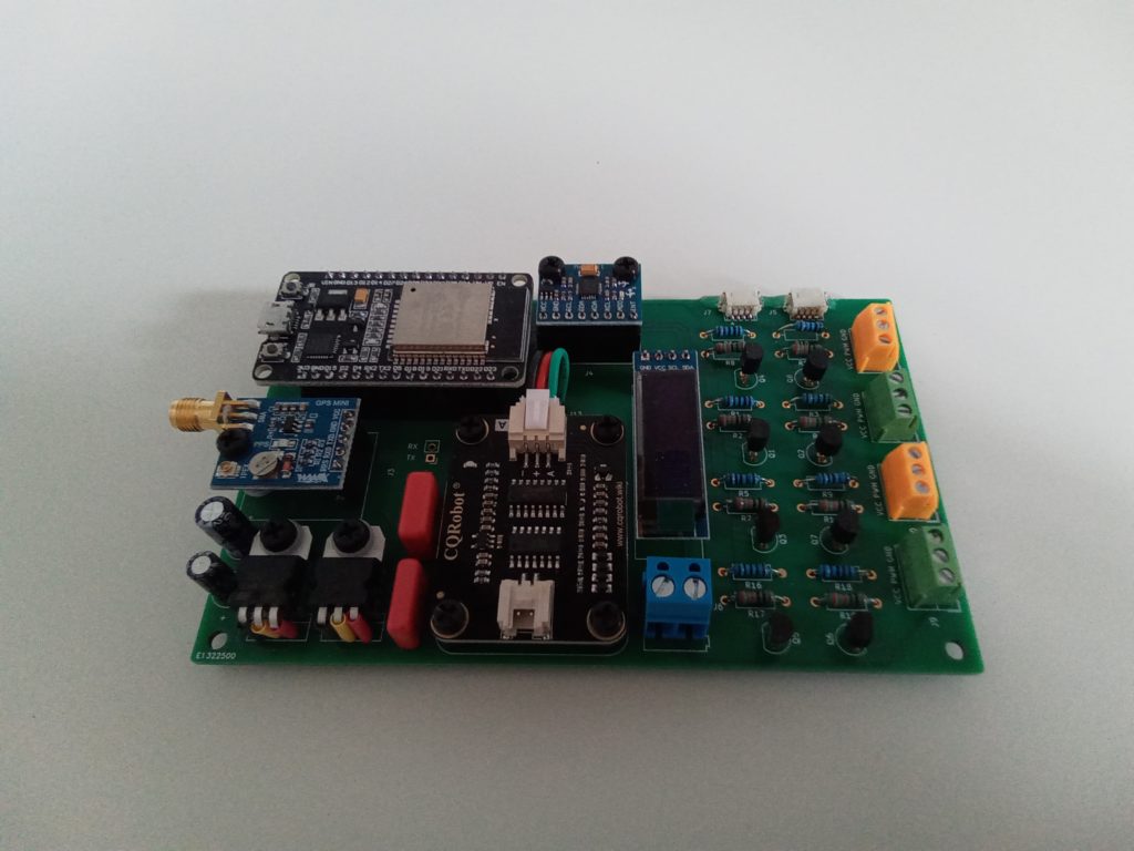
The System Controller consists of a BeagleBone Black microcontroller board and an interface board. The BeagleBone Black is mounted to the backside of the interface board.
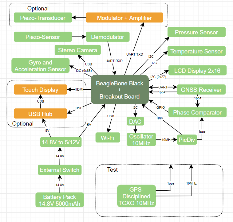
Block Diagram with Interfaces to Sensors and External Components
The two circuit boards are shown in the next picture
BeagleBone Black Micro-Controller and Interface Board
The circuit diagram of the interface board is shown below: